

Week 11
Week 11:
Machine Design
Assignment:
Automate your machine. Document the group project & your individual contribution.
Machine: Sensing & actuation
Input: Sensor, Actuators
Stepper Motors: Measure position
Static: Consistent
Dynamic: Machine that bends and forms
PID: Proportional Integral Derivative. One input where you are now, the other where you want to be.
How to tell the Machine what do to:
G-codes: Were used by early photo plotters. Series of letters followed by numbers. No universal g-codes. Most common and what we used in Fab Mods.
Hpgl: Bracket plotters. Some milling/lasers use this.
OpenSBP: Shop Bot format.
TinyG: AVR processes-board that includes the interpreter for the file. Stepper motor controllers & loop in software. Docs has files.
Programming/Linus/Gestalt/Python/Pyserial/FabNet Board - All of this!:
I started this week by looking at length at the documents that were on Machines that Make to help understand the process. The following links were some of the places that I looked:
http://archive.monograph.io/james/m-mtm
http://mtm.cba.mit.edu/machines/science/
http://fabacademy.org/archives/2015/doc/MachineMakingNotes.html
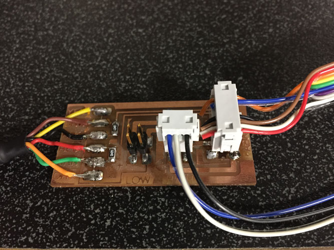
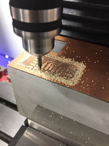
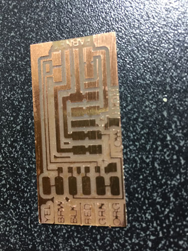
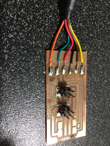
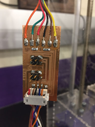
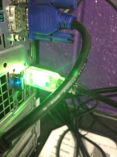
I learned that no matter what meathod we chose, we would need the FABNET board so it was off to the mill, warmed up my soldering iron and made a bunch of 10pos ribbon cables.
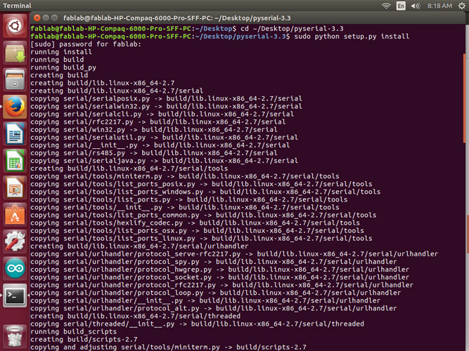
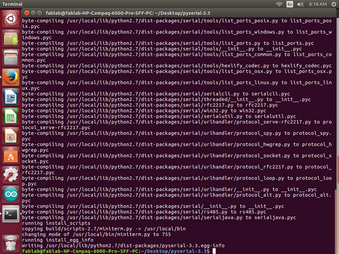
Once I finished with my research I jumped in on my Terminal.
I downloaded pyserial 3.3, unzipped and installed it.
I created a directory for where I wanted my makefile and gestalt to be. I downloaded the correct library from Github for Gestalt and installed it.
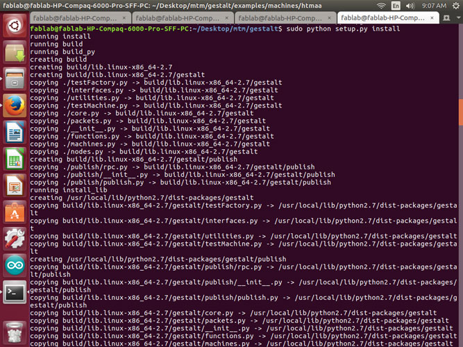
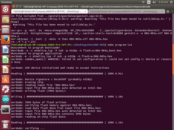
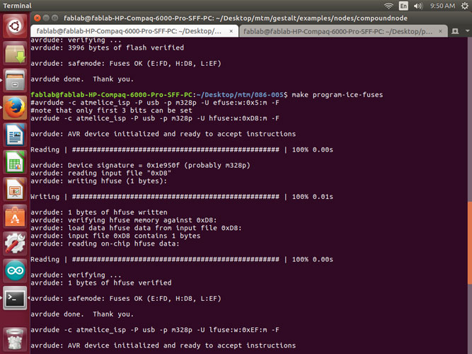
I then cd’d into the folder where the make file was placed and then ran the make file for the gestalt board with the correct language for the Atmel_Ice.
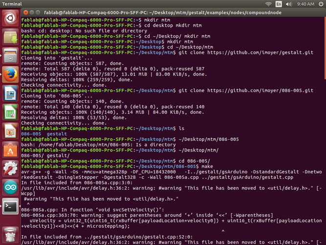
Then I cd’d into the folder where the single_node.py file was located to test the axis and connection.
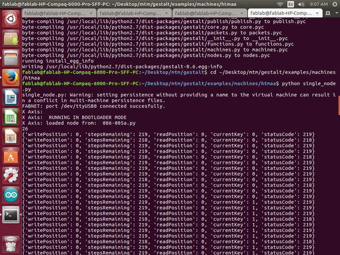
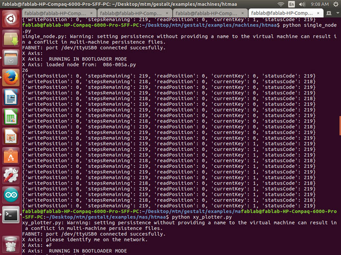
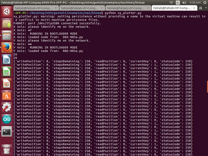
I received multiple different situations along the way.
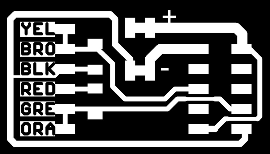
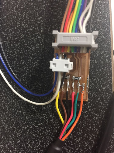
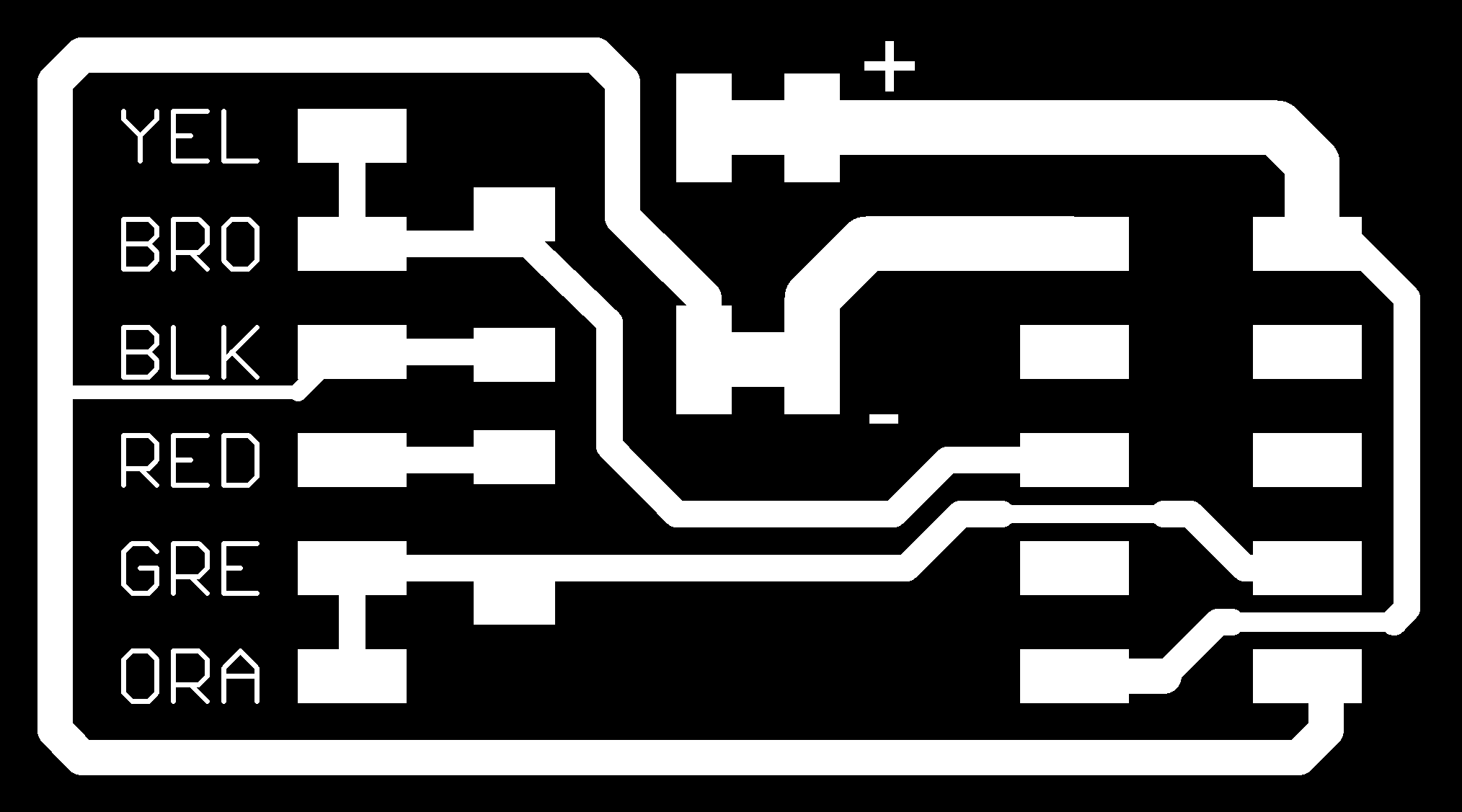
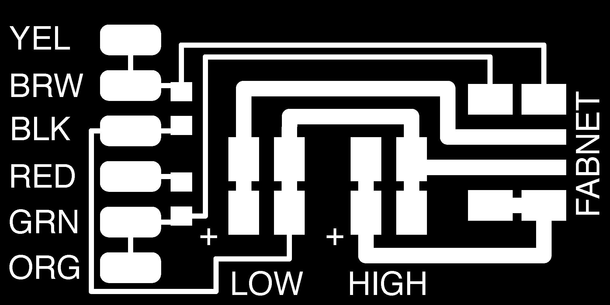
I double checked my connection on the FABNET 8pos cable to make sure the GND's were in the right place along with the High V and 7.5 V. My pinout is below:
1-Red 2-White (High V) 3-Brown 4-Black (GNG) 5-Empty 6-Empty 7-Blue 8-Orange (RS-485A)
I Also checked the other end of the cable to make sure that the 10pos was correct.
I opened the Makefile I was using to flash your board and checked to make sure the 'bootloader' code is commented and the 'application' is uncommented. It looked like this:
#bootloader
#PROJECT = 086-005a_boot
#ADDRESS = 0x7000
#GESTALT_DEFS = -DstandardGestalt -Dbootloader -DsingleStepper -Dgestalt328 -DnetworkedGestalt
#application program, uncomment if you want to use this instead.
PROJECT = 086-005a
ADDRESS = 0x0000
GESTALT_DEFS = -DstandardGestalt -DnetworkedGestalt -DsingleStepper -Dgestalt328
I deleted the file 'test.vmp' and rand the python program again. I also tried reflashing the node. Making sure I used the correct Makefile.
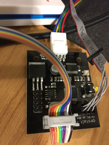
Once none of that would work and it was still running in bootloader mode. I decided to make the new FABNET board and check all other cable connections.
http://mtm.cba.mit.edu/fabinabox/dev/fabnet/overview.html
http://mtm.cba.mit.edu/fabinabox/dev/fabnet/files.html
This used the ribbon cable that runs straight through. We tested the power to make sure we had our positive and negative pinouts in the right direction. Once I ran the single node again, this is what I got. We ran the single_node.py multiple times, one attempt we did get the blue light to blink (Click here for video) on the board, but the terminal still said it could not reach the virtual node.
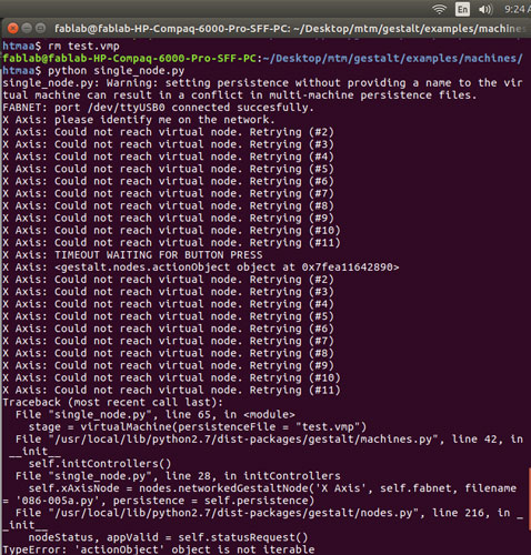
This is where our progress is! We have tried a million things. If anyone has any ideas please help!
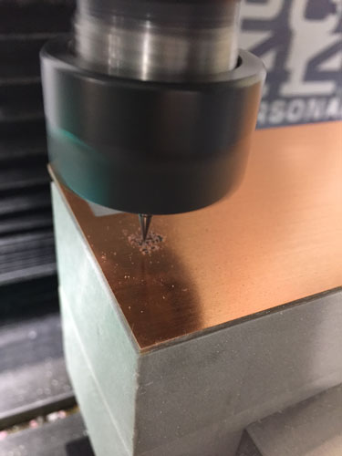
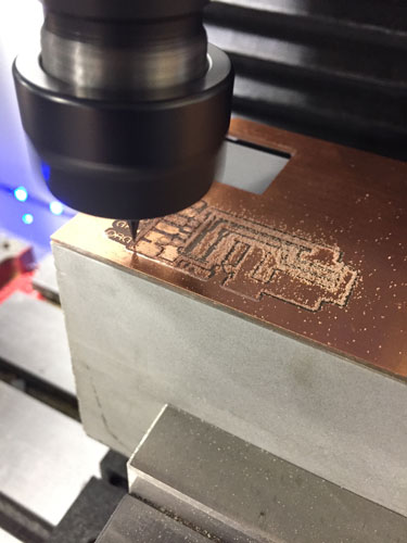
Week 11 Photos